Of course there are many types of signals: "steady" or slowly-varying (ie. "dc") voltages and currents, voltage "pulses" (the signal being the number of pulses in a given time - pulse rate, effectively a frequency signal), and so forth. Modern loggers also accept digital signals as input.
But we'll focus on the basics. A basic logger offers voltage receivers and pulse counters (we therefore need to provide external circuitry to convert current signals to voltage signals, for such loggers). These are configurable in software. What does that mean?
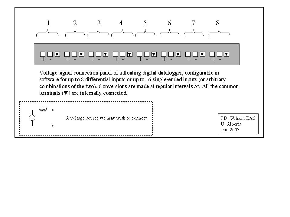
Consider the schematic of the voltage input panel of a data logger. This is a floating logger, which means it is quite flexible. Of course we can ground it, by connecting any one of the ground terminals to power-line ground.
Now suppose we have a voltage signal (of the type shown schematically on the figure) - the signal is the voltage difference on the two wires, ie. we want to measure the voltage across the ends. We don't know perhaps, if the source floats or is grounded - but as long as the logger is floating, that doesn't matter. There seems in this case no reason not to choose to configure a single-ended input. So we connect our signal across, say, the 1+ (the "hi" terminal, or input, labelled 1), and the logger common: we shall have selected single-ended input channel 1.
Now if we had a second voltage input of the same type, maybe we would put it across the terminal 1- ("lo" terminal numbered 1) and common, which is s.e. channel two. Alternatively, we might have chosen to use s.e. channel 16, which is the connexion across 8- to common.
If on the other hand our signal source was powered by the logger, so that it shared the same ground, and if that "source" was the error voltage of a Wheatstone Bridge, then we'd need to use a differential voltage input (so that each terminal of the source would see a high resistance to common).
In short, we shall have to tell the logger program the sampling interval Dt and for each voltage signal we shall have to tell it
Note that there is (usually) an ASSOCIATION between an input storage location (where to store in memory) and an input channel number (what physical location on the input panel the signal wires are hooked into), but these numbers refer to different "attributes" of the measurement system, and need not be the same.
"Intermediate processing instructions" can be used to pull numbers out of input storage locations, perform mathematical operations on them, and plop into another input storage location. Again, results of the computations are refreshed every Dt.
There is much more to programming the logger. We may wish to perform mathematical processing of the signal, and average over a time Tavg... virtually any statistic of any function of the signal can be computed.